Mechanical Design
We had several key concerns with regards to the mechanical design of the system. The cylinder had to be able to smoothly rotate at each independent section and be easily operated by the user. We also needed a way to trigger the solution internally at each rotating section.
Firstly, we decided to create the smooth rotation using bearings, a rotating bearing mounted on the outer cylinder and a stationary one to the interior central shaft. We also made the decision to only use one pair of bearings per section to minimize obstructing the emitted light of the cylinder.
As opposed to the original design, which had the cylinder sections lining up with each other to be solved, we had them align with illuminated stationary sections between each rotating section.This allows us to focus on the mechanical and electronic components of each section independently.
To trigger the solutions to the puzzle we chose to abandon our initial concept, which called for each section to complete a circuit using electrical contact surfaces. Instead we used electrical snap switches mounted to the bearing surfaces which are triggered as each section is properly aligned.
Fabrication and Assembly
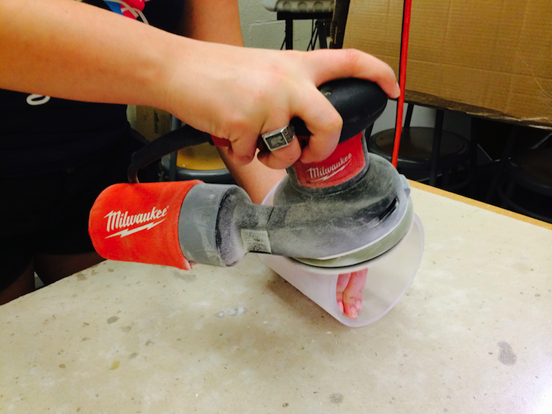
We chose to create the cylinder using a 5” acrylic tube which we sanded and applied our puzzle design to. The outside finishing on the acrylic was an attempt at a frosted outside for the lights to shine through in a diffused manner. We layered hand sanding with an electric sander (about 10 passes) and then finished it off with a frosted glass spray paint.
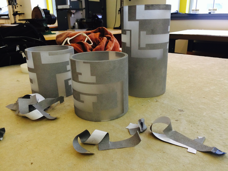
The puzzle imprint on the outside of the acrylic wanted to be as seamless as possible. We cut vinyl decals of the puzzle maze, used transfer paper to align them onto the three independent sections of the cylinder, sprayed multiple layers of silver paint over the decals, let dry, and then removed for a near seamless puzzle maze.
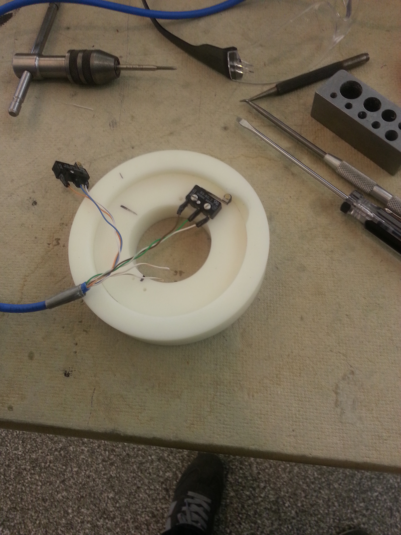
The acrylic was separated into 3 rotating sections and 2 stationary alignment sections. Inside of these rotating sections we used delrin to form the bearings after carefully machining them on the mill.
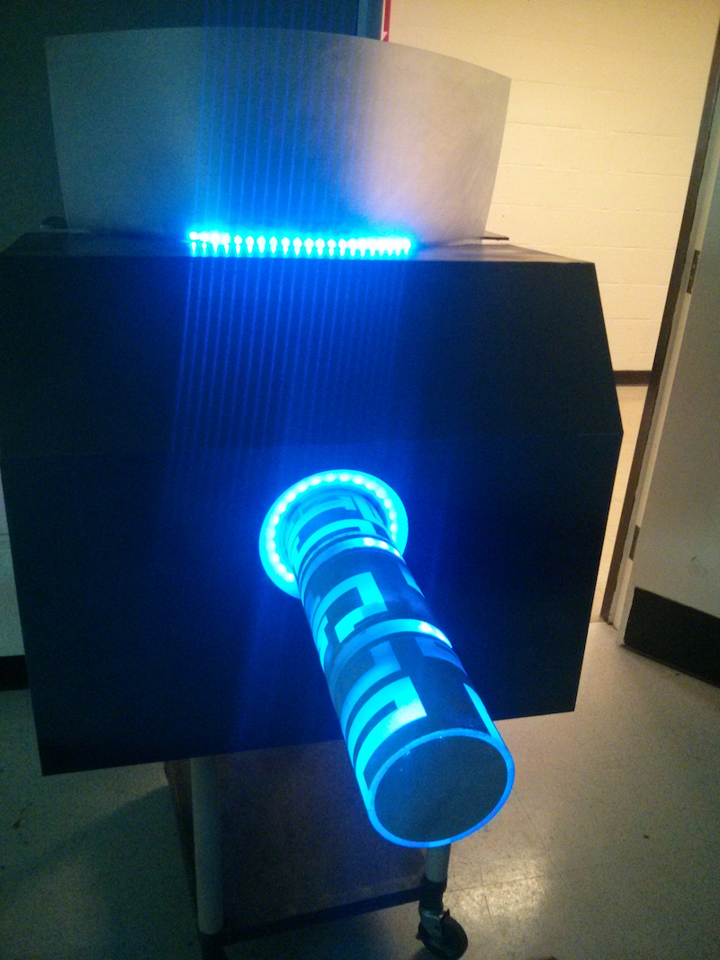
We then wired all electronics through the central PVC shaft including the various LED strips and our alignment switches and ran them through machined holes in the shaft. The switches were mounted between the inner and outer bearings where a groove was machined to actuate the switch when correctly oriented. We attached the components of the cylinder together using adhesive. We mounted the LEDs throughout the device to the shaft and stationary sections using tape. Once the pieces were assembled, we then inserted the entire device into a wooden box with a sci-fi foam facade. The device was powered up and tested section-by-section to check the functionality.
Here we see the finished model being tested with functional lights and switches:
Future Improvements
In future iterations (specifically, with a longer timeline for high-end manufacturing processing and with a bigger budget), we would be able to incorporate elements that would grant the final touches to make the user really immersed in the experience. The three key areas to focus on here would be the actuators, the material finishings, and the robustness.
- Ejection and Insertion Mechanisms in a future iteration. These actuators would sit similar to where Jessica’s original sketch model placed them.
- Materials would be upgraded to have a nicer, sleeker feel that is more “futuristically sci-fi” in order to go with the experience of pneumatic cylinders ejecting automatically from a center console, such as sandblasted front panels and brushed chrome cylinders.
- Robustness for the system so that it can withhold curious youngins (and adults) that try to yank the cylinder out of the center console and into their own hands.